Noodle’s Gripping Toes

noodleTOES

For the past year, the four tawny stalks that NoodleFeet balances upon have remained common pool floaties, 2.5 inches in diameter, hollow, providing nothing more than the obvious support needed to function as legs… but Noodle longs for something greater.

GRIPPING TOES

When Noodle feels threatened, there is little he can do to defend himself. He can beep and perhaps canter away at a slow speed… but he is passive and therefore vulnerable. He isn’t equipped to handle the harrowing task of world domination::cough:: I mean, daily life. To fix this, I decided to add another layer of complexity to Noodle’s most important characteristic: RETRACTABLE GRIPPING TOES for his feet.

A while back, I came across a video of a rock drilling probe concept by JPL. This neat claw attaches itself to a surface by splaying out a hundred or so mini grappling hooks in all directions, which catch on the rock and help anchor the central cylindrical drill in place. I saw this and thought to myself… Noodle needs four of these, as shoes.

Like a good mother, I started brainstorming how to create said shoes. Originally I designed long claw-like toes that rotated out and back, sort of like switch-blades:

Screen Shot 2015-11-11 at 1.50.32 PM

IMG_6632

They fit into Noodle’s original 2.5″ diameter noodle material, and even added stability… but there wasn’t enough area to actually install any motors to actuate things.

With a little bit of trial and error I rethought the whole design and came up with a solution that made use of 3D printed plastic’s flexibility. This new concept worked more like a cat’s retractable claw, and was similar to the drill from the video that had inspired me.

toe1

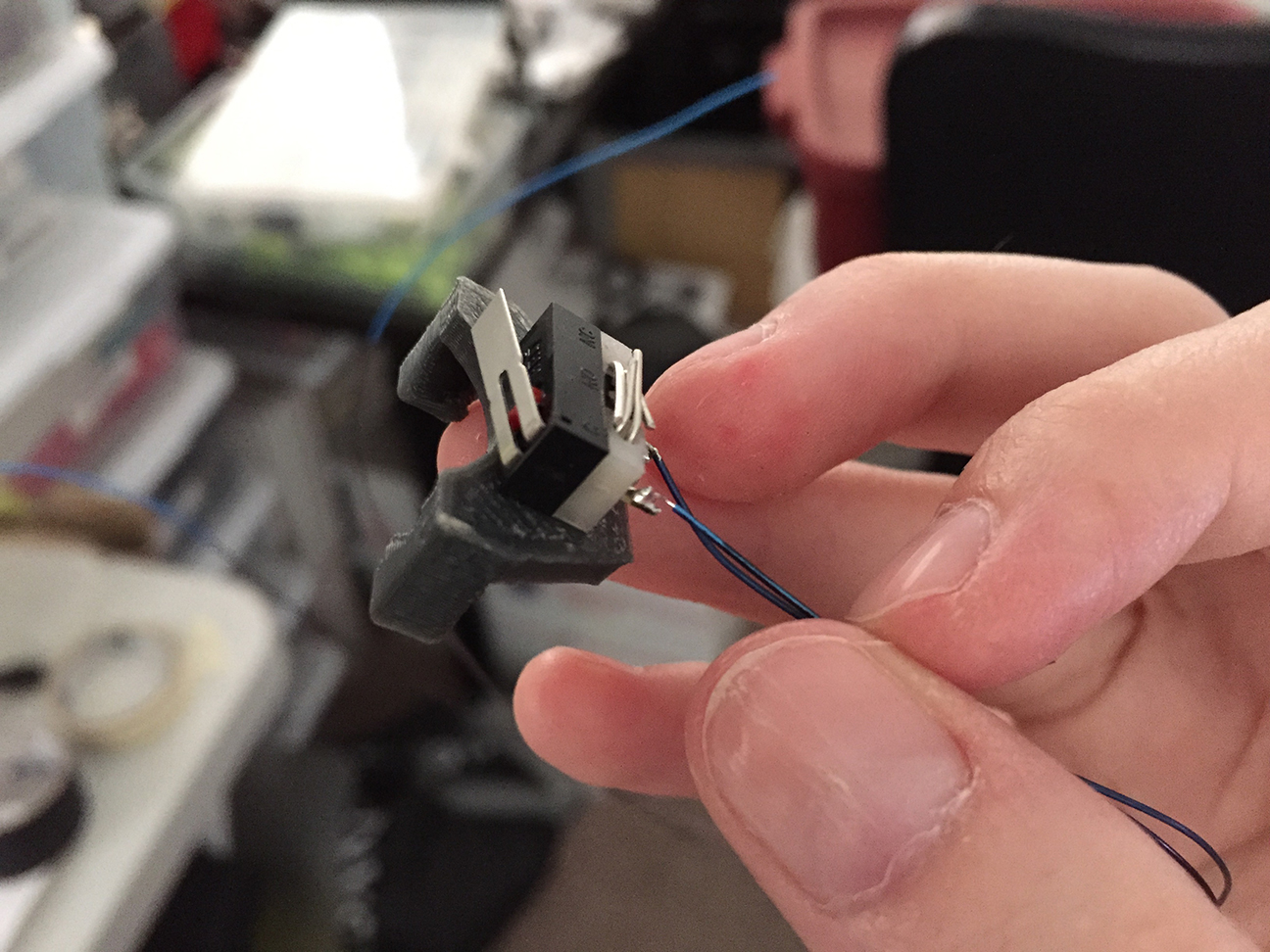
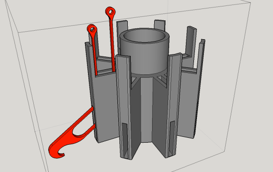
Each individual toe (in red) would be forced through a curved internal channel and out the side via two thin bendable “tendons”:

Screen Shot 2015-11-12 at 2.23.46 PM

How The “Tendons” Work

An individual toe has two strands of tendon attached to the back. When the tendons are pulled in opposite directions, it causes the toe to torque upwards or downwards.

Why Do the Toes Need to Tilt Back and Forth?

If the toe goes straight back into the sheath the way it came out, it won’t unhook from whatever its currently gripping. Also, the tip of the toe will likely snag on the edge of the sheath on its way back in. To properly “detach”, the toe should arc upwards slightly as it retracts.

My first prototypes were designed to fit inside the 2.5” diameter noodle material. I was able to make it work, but it didn’t leave much room for the other future functions of his feet (his tongue):

IMG_6656

IMG_6831

In the end I really needed more space to fit moving parts and hardware. Luckily I have a noodle fairy living with me (Mark) who harvested a larger piece of noodle stock from a pile in his garage. It is 4” in diameter and offers me much more room to play around with! Plus, fatter feet will give Noodle more stability!

IMG_6803

4″ PRO-TOE-TYPE 1.0

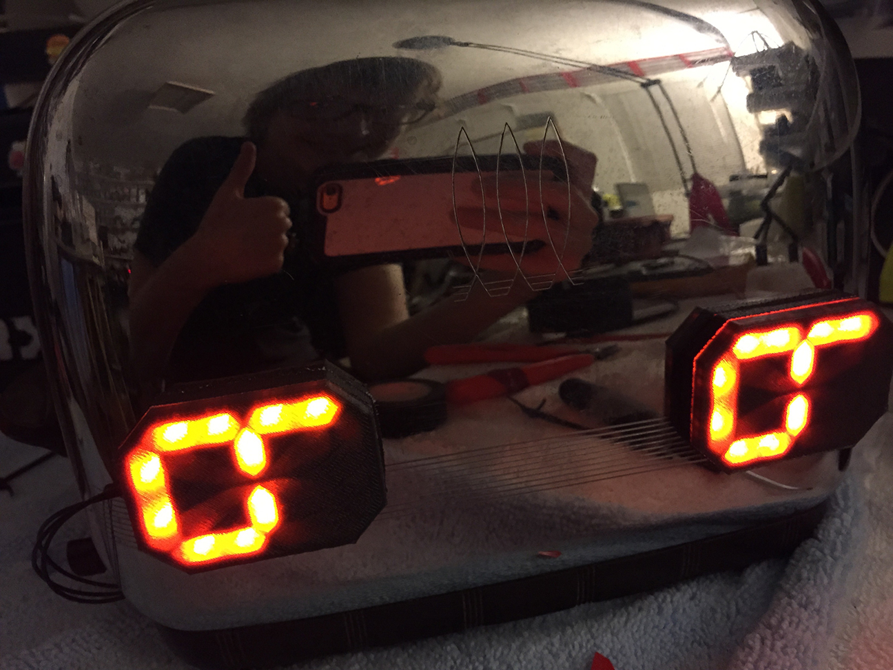
I tweaked my design for the new 4” material and printed my first prototype with a set of eight twinkling magenta toes (I haven’t ordered red filament yet).

IMG_6812

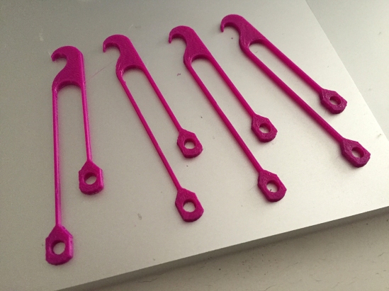
The reason for the tendons being slightly different in length is so that when they are fixed next to one another, it creates the needed outward/upward tilt:

IMG_6840

(so, this is what a toe flower looks like):

IMG_6805

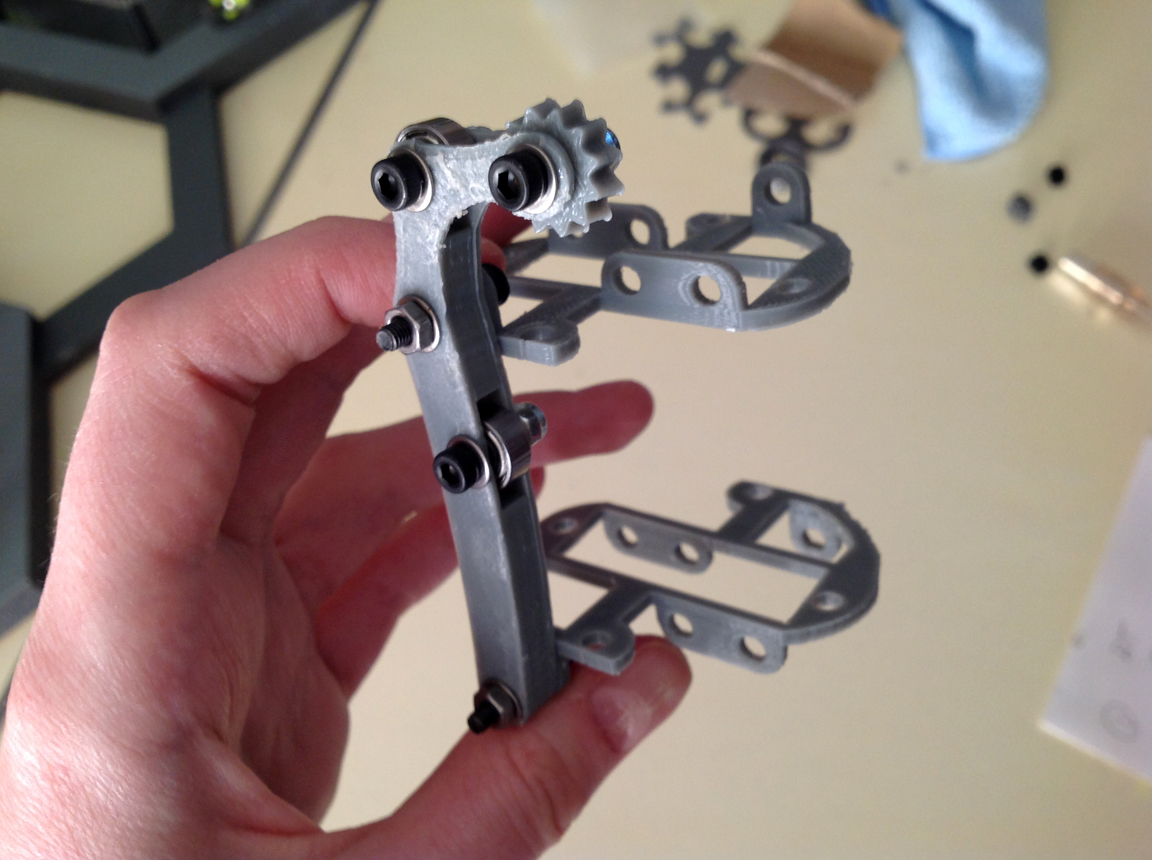
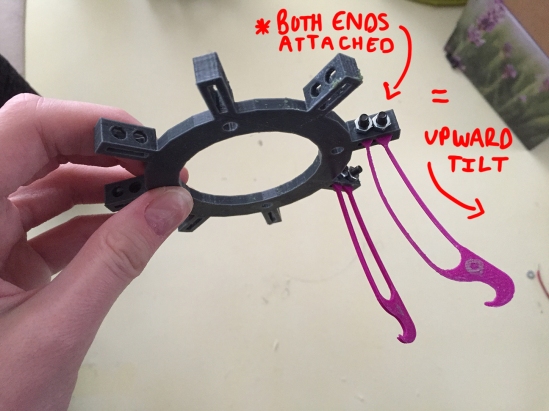
I originally planned to connect both tendons of each toe to a common ring piece (above). When the ring is pushed downward towards the sheath, it would force all of the toes through their channels and outward at the same time. I also added a spring and guide rod (a long screw) below the ring to push it up again once downward force is removed:

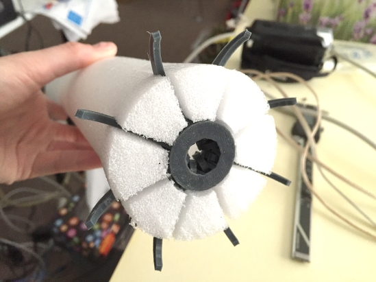
The first complete 4″ prototype worked more or less… It certainly passed the “carpet snagging” test:

I learned right away that I couldn’t actually connect both tendons to the same ring and run it through the inside of the sheath without it binding (which now seems pretty obvious). The only way I could get the above demonstration to work was if I left the longer set of tendons sticking out freely, attached to nothing… so that the toe has no preset angle bias as it attempts to travel through the channel:

IMG_6837

However, in order to make it work at this point, all the little purple pieces sticking out had to be pressed down together at the same time first, or else everything would bind up and destroy itself.
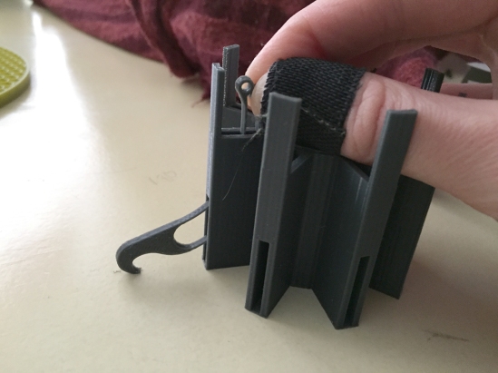
4″ PRO-TOE-TYPE 2.0

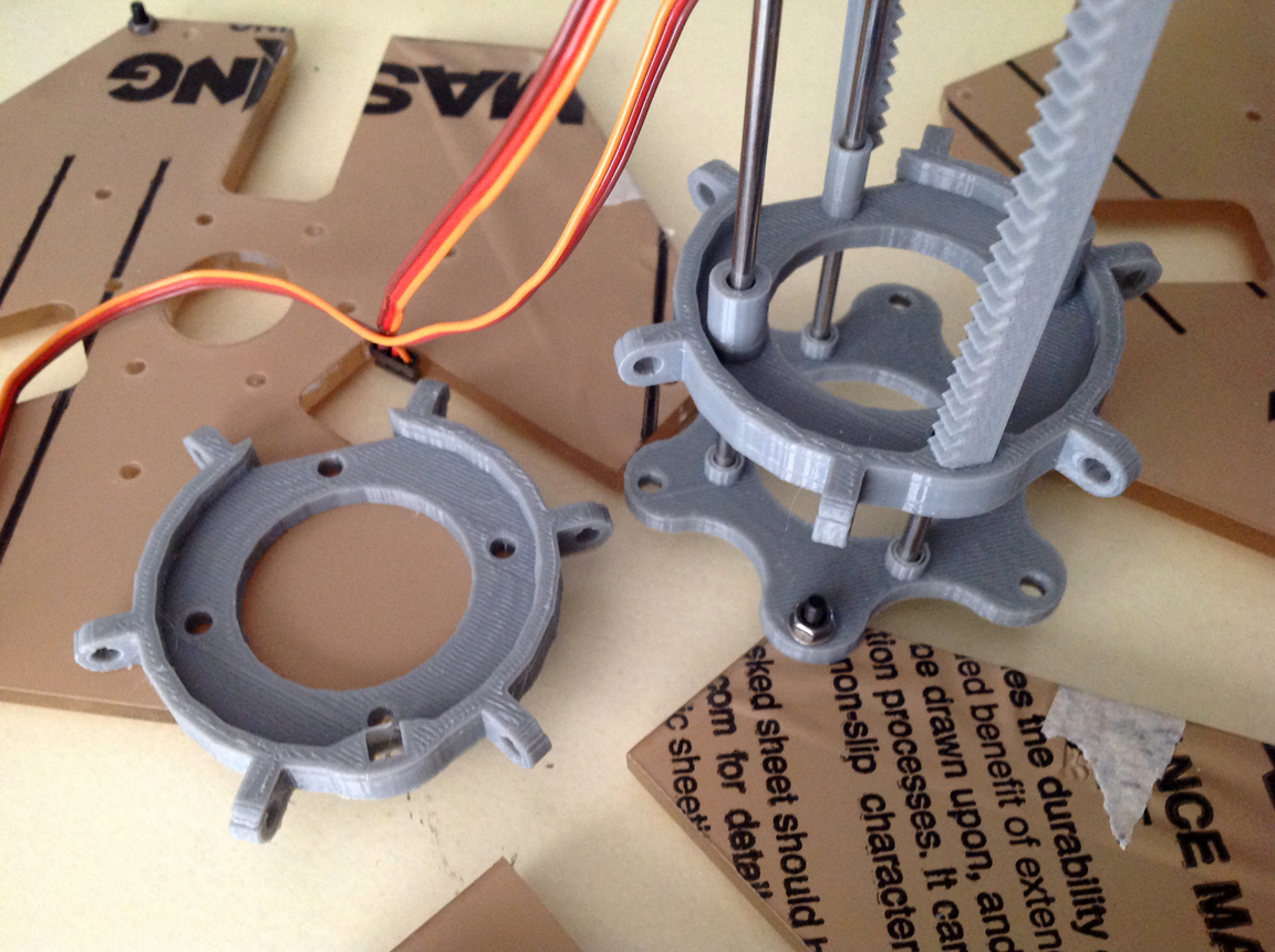
Each tendon should be attached to its own independent ring…

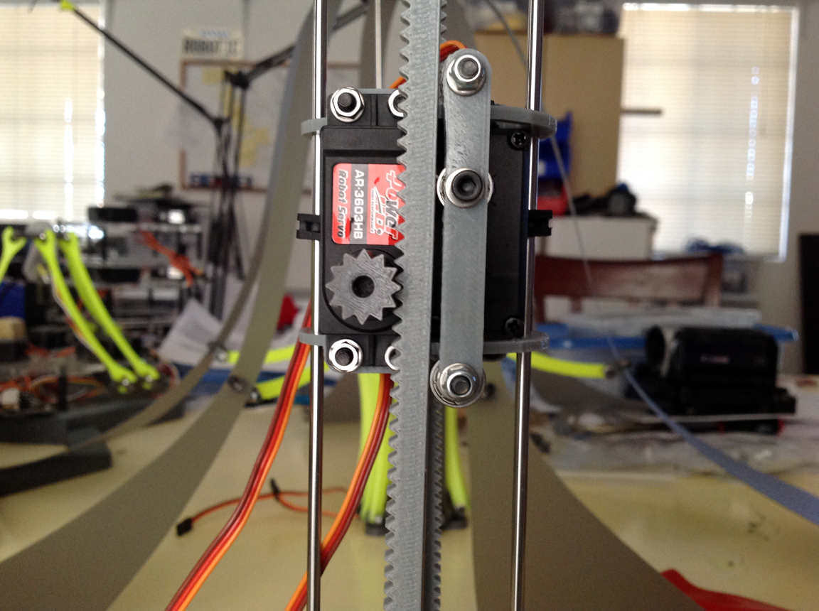
…so that when the ring attached to the inner set of tendons is pressed downward, it causes the toes to tilt upward first as they begin to move down through the channels. Then the top ring hits the second ring below it which the outer tendons are attached to, and then the two travel together pushing the toes outward the rest of the way while maintaining the slight upward torque. This allows the toes to torque gradually as they travel through the channels, without binding up:

IMG_6818

This second prototype (above) is more or less final. I’m going to fine tune it from here, but something very much like this will end up as Noodle’s toe-feet.

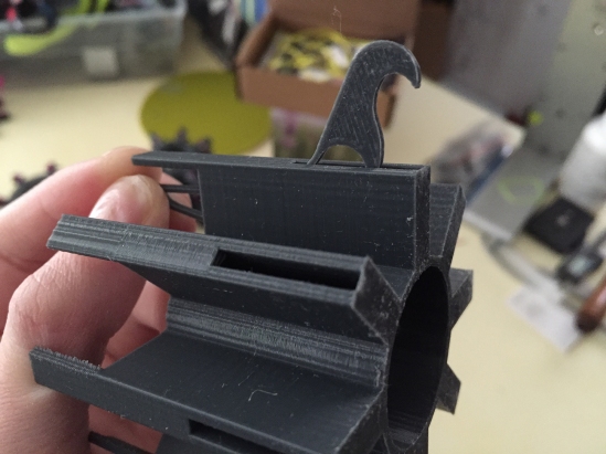
The greatest part about this design is that I have nearly 36mm wide of space in the middle to fit his secondary foot function! … ( ? ) … Which is tasting if you didn’t know!

Stay tuned for my next post on the development of Noodle’s TASTING FEET; small silicon wedges that will salivate and lick:

Screen Shot 2015-12-06 at 12.19.14 PM

As I typed that it just occurred to me that I’m pretty much making a tube that can grip onto something while licking and drooling on it. -heh- He’ll have four of these devices. Noodle will be feared by other robots his age.

The only downside to these new complex feet is that I’ll likely have to learn to knit him a pair of custom socks for Christmas. (and I think I actually will) ❤

Read about my past progress on NoodleFeet on my website!

More to come soon!

Eye of Toast

IMG_2187.JPG

I would like you to meet my toaster. The toaster is an old character of mine who has survived through subtle reference in the things I draw and build. Nothing I make is about the toaster, but the toaster is about everything I make. He’s my chrome totem.

While I was in college abroad, I bought an actual physical model from the early 30s off eBay which looked pretty much identical to the one from my doodles (still works too!). I had big plans for this little toaster, but at some point we got separated during my move back to Las Vegas.
The toaster got packed in one of my friend’s moving boxes and it wasn’t until this summer that we finally remembered to unearth him for me to take home. After three years of waiting, toaster is now happily sitting next to me on my bench…

It’s wonderful to be reunited, but admittedly it feels weird talking to him during the day without a set of eyes to look into. So… I decided to fix this.

Not just any eyes will do either. They have to be capable of showing a multitude of expressions, particularly the sly and judgmental sort. Instead of using an LED matrix to form shapes, I thought it’d be a bit cooler to make my own modified segment display. Once turned on their side, a standard twelve segment display is capable of showing not only numbers, but all of the expressions a toaster might make too!

CUSTOM BOARD MAKE!

Again I took to Eagle CAD and prepared a board which I’ve called, “EYE OF TOAST”. You can see where the segments are- and where the LEDs will be installed.

Screen Shot 2015-08-11 at 9.49.16 PM

3D PRINTED EYE FIXTURES

While these boards were off being fabricated with OSH Park, I worked on designing the fixture piece that the board would sit inside of. It would need to be as thin as possible, yet also able to defuse the two point sources of light in each segment… this took a few revisions.

IMG_5910

My first prototype was a dual extrusion piece (the two-tone ones). These worked alright, but the white obviously stands out a bit too much when the segments aren’t in use.

I printed another solid gray fixture with a seamless .5mm layer on top, so that the light can pass through just fine, but when the LED is off, it disappears (bottom left). This was our winner.

THE MANY EMOTIONS OF TOAST

Additionally, while I waited for the boards to arrive in the mail, I brainstormed what the actual emotions would look like. I printed out a sheet of paper filled with pairs of segmented eyes and started coloring them in, just like an assignment in kindergarten. It was amazing how many different expressions I was able to muster from these 24 lines!

toastEye2

Once my happy purple envelope arrived, I got busy soldering all the tiny bits in their proper place. Since there have been a lot of ATMEGA328s floating around my life lately, this was the chip I decided to use for this project. So, I’ll be programming in the Arduino environment also.

toastEye1

PROGRAMMING ARRAYS!

I learned all about arrays for this project… which Mark held my hand through (and at times told me to step aside so he could just get things working).

Once I made ints for all of the expression I drew up on my toast ‘homework’ sheet, I could then call them easily in my sketch without having to type a bunch of numbers each time. The function I’m adding to the toaster is that he cycle through expressions every time you pull down on his lever. So, we added a switch to the code as a toggle button.

TOASTER SURGERY

After the code was tested and finally working correctly, the next step was to install everything on the actual toaster itself… which is where things got a little scary for me. I decided that this wasn’t the time and place to cut into toaster’s pristine shiny casing in order to permanently install the eye fixtures. Instead, I’d be attaching them onto the surface of the casing. Less cool, but less risk.

  • This meant I was going to need to run wires from the eyes on the surface into the guts of the toaster wherever the power supply was going to live. I decided on using a USB rechargeable 5V battery; one that is flat, slim, and can easily slide into the toasting chamber like bread.
  • I would also need to install the limit switch somewhere along the moving parts of the lever, yet preferably in a place that isn’t visible from the outside.

For the internal installments, I prepped a soft and well lit area for toaster’s opening and began my descent into century old crumbs and rust.

IMG_5930

The first layer of defense wasn’t too hard to break through… it was held on by some screws:

IMG_5937

Once the “crumb guard” was off, I was able to remove the plastic ring around the bottom of the casing:

IMG_5943

At this point I already found a possible location to install my limit switch. It was near this lever bit in the middle that had some motion, yet not so much motion that the switch may be missed completely or dislodged.

I designed and printed a little bracket to clamp in place between the two bread slots:

IMG_5947

Here it is installed. The lever actuates just enough to press it:

IMG_5959

I could have been done at this point… but some part of me wanted to get the rest of the toaster dismantled just because. ANNOYINGLY there were a few things in the way which were preventing me from removing the chrome outer shell from the heating element inside. One of those things was the toaster’s plastic lever arm, the other was his twist knob. They were effectively pinning the casing to the guts within.

IMG_5963

The plastic arm on the lever was easy enough to detach as it was held on with a set-screw. The twisty bit however appeared to be press-fit in place and impossible to remove… which was bad pizza. It took an hour of careful twisting, pulling, and fondling before the age-old grime crumbled loose and we discovered there was a pin on the end of the knob that could unscrew. Once we finally figure this out the case slid off with ease (and allowed a bunch of others piece to fall out of place-heh):

IMG_5986

From this point on, toaster got to watch me perform a deep cleaning on the rest of his insides, which were caked in rust and chunks of buttery, burnt bread crumbs.

IMG_6027

I took care to save all of these crumbs that I removed in a little plastic baggy… as I believe if you are a hundred-year-old toaster, your bread crumbs are kinda like your soul. Besides, I’d have felt bad discarding crumbs that have survived in this world three times longer than I have.

After a nice cleaning, I put everything back together… which was A LOT harder than taking it apart. Nothing wanted to slide into place quite right and there were also these long steel pins that came dislodged from the inside, which I had to re-thread with a pair of players and a flashlight. =/ In the end though, I got him back in one piece with the wires to his new augmentations ready for hookup:

IMG_6002

The last step was to measure, cut, and solder these wires to their appropriate pins on the eye PCBs. Afterwards, I added little squares of double-sided silicon tap to the back of the eyes and stuck them onto the casing:

IMG_6008

I carefully added a thin ribbon of gaff tape along the seam where the eye fixture meets the chrome as to seal off any light from leaking out:

IMG_6023

TOASTER has never looked so happy or sarcastic! I was relieved to see that everything worked as expected once he was plugged in. The switch I installed functions perfectly and the expressions have just the right effect.

IMG_6031

I’VE COME TO REALIZE

Toasters are complicated little machines! I’ve seen toasters on sale for under ten dollars in ‘dorm essential’ sections of stores, and this feels shocking to me now. It’s true, they seem so basic and primitive… you press the lever, bread goes down, some heat happens, and then the bread goes up again. They aren’t channeling the entirety of human necessity like smart phones, and for that they are easily taken for granted. HOWEVER, there was a lot of engineering involved in the creation of these little mechanical devices that serve to warm our shitty bread without fail time and time again- and they haven’t changed much over the years. I believe there is a whole movie about this! WAIT- Yes. It’s called The Brave Little Toaster. I think I shall go watch it now for nostalgia’s sake.

As a child, that movie gave me my love of all inanimate objects. Once I saw it for the first time, everything on earth was alive. Cheers to that old seed…

AND hug your toaster next time you see it. It’s a work of art.

IF I WERE TO DO IT AGAIN…

…I would likely buy a new toaster that was designed to look vintage and permanently install the eyes in the casing itself instead of just adhering them on the outside. I’m willing to bet that a newer model would be made of a thinner metal, thus easier to alter, unlike my classic toaster’s blasting shield of a chassis.

There was also the idea of cutting micro holes for the light to pass through on the surface of the case so that the LED fixtures could be mounted inside. This would make the toaster look completely unaltered when the LEDs are off, and when in use the chrome would appear to illuminate like magic (or the charge light on your Macbook).

IN THE END

Alas! Another physical manifestation of a creature from the graphite dimension! If you wish to know the back story of toaster, NoodleFeet, and all of the other things I build, check out my webcomic GravityRoad; ideas begin in 2D.

Light Play : Half Way There

April

I’m tired. I will forever look at big art installations and wonder with silent reverence if there were two people at some point sitting on their couch at three in the morning assembling parts to the thing by hand.

Any how… WE’RE HALF WAY THERE! Two days ago everything came together at last. One by one we tested and plugged the new babies into their happy little nests. We even named a whole pallet after our favorite characters from Create TV, which we’ve had on in the background while doing a lot of the manual labor.

deltas42pano

Long story short, Mark fired up his Netbeans GUI and everything just worked. With a little tweaking over the weekend we got the 42 little ones to behave more or less like we were imagining. Mark even figure out how to turn off the stupid thing in the Kinect example code that waits for a hand wave before tracking. This means, it will just follow any hands it sees all on its own. Wish we knew about this last year >.<

After our appearance at the Science and Technology Festival tonight, the countdown resets for the big Maker Faire in a little less than three weeks. We have another six pallets to ready before then… not to mention the challenge of solving exactly how we’re going to get a gang of robots all the way up to Silicon Valley safely.

Wish us luck or something. After May is over I’m going to curl up in a blanket with my soft delta and watch the hobbit… and I don’t mean Mark. 😉

The art beast is a monster that wears its own face as a mask. We’ve gotten acquainted over the years, but as much as I think I know it, at the end of the day there is something else underneath that I can’t see. So in reality, I still know nothing of art.

noodleFeet : Looks Like a Noodle

HEAD : I can’t find a damn semi-transparent mixing bowl to appropriate as Noodle’s noggin. So, I went with a plastic bowl I bought a while back because it was Robot Army gray and yellow. The size isn’t right, but tilted at an angle with his eyes poking out it looks a lot like a helmet… and I’m okay with that.

SHOULDERS : I went to the store with Mark yesterday and searched through all of the collars in the pet isle to find a replacement for his old harness which no longer fits around his new planetary gear assembly. There were many small kitty-sized bands with big jingly bells… but not a single one was in neon yellow. So I didn’t bother getting any.

In leu, I smashed noodle’s old harness back onto his gear box so that if needed I can still hook him into the leash hanging from the ceiling above the work table. It lacks a proper bell… but fashion is second to safety.

KNEES : I think noodle needs socks.

TOES : He needs socks because I still haven’t been able to locate some of those stupid squishy stress balls which I plan to halve and mount to the bottom of each of noodle’s feet. These should help give him some traction as he attempts to walk. Someone pointed out that the foam material of the noodle was just sliding on the smooth surface of our table which was why he didn’t get very far during his first test run…er- walk.

Any how… the socks will keep the bottoms of his noodles clean until they’re capped with said squishy foam balls… Because tomorrow I’m taking noodle on his first ever outing into the big wide world.

He’s far enough along to show off at this point, walking or not. Speaking of walking… here’s some footage of him taking his first steps:

Light Play : Brains Nerves and Butts

This past weekend Mark and I got a bunch more work done for the installation. We finished glueing and painting all the shiny black honeycomb pallets, so all twelve of them are now stacked neatly waiting to receive delta babies. …which means we need to build lots… and LOTs of delta babies. Thankfully, as I sit here and write this, that part is mostly done. For the past week or so the living room has transformed into a birthing chamber of plastic bins and Create TV.

IMG_1726

At an average of 15-20 minutes a piece, we built around 50ish more base assemblies. That’s the acrylic bit with the three motors attached.

IMG_1748

Obviously, they aren’t full deltas yet. They’re missing their snazzy yellow arms and blinky LED on top, but we wanted to get the hard part out-of-the-way first. The next step is to calibrate all of these little delta butts, and then screw all the grey paddles onto the gear hubs. >.< Which will also take a bit of doing.

Mark spent a crap load of time crimping custom cables which will tie the deltas together as one big happy collective consciousness. These will connect a series of relay boards to the individual brain PCBs of each robot:

IMG_1705

So yeah, brains…. less exciting, I’m soldering brains again. Boo. With all the other cool things to work on, its monotonous melting all the same pieces over and over to blank PCBs… but alas, it must be done sooner rather than later.

As the brains are tested and flashed with all of the knowledge of how to be a good little inverse kinematic thinking soldier… we’ll be gifting each baby with a brain one by one, and then adding them to their shiny honey comb home to dance the mightiest robot dance.

I even squeezed out some new art which we had sent away to become postcards. We’ll be handing them out wherever we happen to show things at for the rest of the year. I say all of this tantric preparation does sorta feel like jumping out of a plane with a skirt on… so the image is appropriate. PROPAGANDA!

Campaign15PRINTFILE

Our first gig of the season is in a little less than two weeks during Las Vegas’ Science and Technology Festival. Here we come!


Light Play : Spawning for Maker Faire

Maker Faire in San Mateo is imminent! Last year my partner Mark and I showed an installation of 30 delta robots which mimicked the physical gestures of people. All of the robots however did the exact same thing… which was impressive if you’ve never seen them before, but hardly to the extent of awesome I have in mind for the project.

IMG_5181

Though we’ve been working hard, Light Play still has a long way to go development-wise. Until they’re feeding off neural input and hopping through cities in flocks, I’m continuing to slowly expand our numbers. For now, that number is 84, which doesn’t seem like a whole lot in the face of the thousand I dream of having… yet as I sit on the couch night after night building these little monsters, 84 feels plenty enough to my calloused finger-tips:

IMG_1654

This is what takes the most time to assemble. The motors mounted to their acrylic bases:

IMG_1672

Hardware: the biggest hardware upgrade we’ve made this year has been to the bases the robots sit inside of. Their honeycomb-shaped pods have been redesigned with frequent transportation in mind seeing as the wooden ones we made last year took a bit of a beating and were awkward to carry. In addition to holding three less delta robots per pod, the new bases are also made from black ABS… which means they mostly disappear in darkness, are lighter, and also a lot more resistant to bangs and dings.- Oh! And holding seven robots instead of ten makes for a nice round shape too!

IMG_1677

We had these new honeycombs cut professionally at a metal-fab here in town; well worth the extra money not to have to supervise cutting all the shapes ourselves at SYN Shop. Where we did save some time doing this, there is really no getting around glueing the cut pieces together, so Mark and I have been attaching things with ABS weld in his garage a little each day.

When all is done, we’ll be able to lay out these modular pods to fit whatever space we’re showing in. Our setup for Maker Faire this year will consist of 12 pods that are arranged in something of a dome, like this (but one tier higher):

conceptHEX7

Software: I mentioned the robots should be doing interesting things. Yes. Imagine, if each delta robot were a blade of grass in a field, and your movements were the wind… every hop, skip and wiggle you made would send ripples of complex rolling patterns through the field as a response. That’s the end goal, and very much Mark’s department.

The robots are networked with the DMX lighting protocol now. They also have a snazzy GUI which Mark designed in Netbeans to simulate and visualize the behavior of the field. We’re still deciding on what type of sensor will be responsible for capturing input.

The use of the Xbox Kinect last year, though it worked marvelously, became a nightmare from hell. It turned our field into an exhibit more than a curiosity and tied us to the booth explaining to thousands of people one by one how to control the flock… To avoid a similar situation… our setup this year will respond to the environment at large. For people walking up and observing, it won’t be immediately apparent whether or not the robots are reacting to them. This will fuel engagement and hopefully allow us more zen time to detach and enjoy the rest of the show.

Robo Wagon: Like Scooby Do, Robot Army is going to have its own touring transportation of sorts. It might not be an actual van… and probably not as cool as the picture- but in the next month we will figure out a more permanent method of packing and hauling our kinetic circus:

Untitled-1

With less that six weeks left, it’s crunchy again. I’ll find time to post updates when I can… but for now, back to soldering brains. ❤ Oh yeah, while we build the new homes, the deltas are getting acquainted with noodleFeet in the workroom. DAWWWW:

IMG_1646.JPG

noodleFeet : Goes Metal

I’ve relied on 3D printing for so many of my prototypes lately, and have finally come to a point where plastic won’t cut it any longer. I require metal, in this case aluminum. The likes of which I ordered from McMaster-Carr and received in the mail last week. I literally spent the majority of the weekend meditating over how to measure my cuts and holes… as for the first time in a long time, their accuracy and placement was entirely up to me and my calipers, not some Cartesian goo plotter as I’m so spoiled by…

While everyone was downing beer and watching the Stuperbowl, I was in the garage with Mark playing with his father’s ancient drill press. He eyeballed one axis, I checked it against the other, and we were able to punch the 24 holes needed on the four pieces of aluminum tubing which would soon be noodleFeet’s strong new legs.

IMG_1445

As you can see, I printed out little strips of paper with lines where holes needed to be drilled. It only occurred to us immediately after we finished how much easier this would have been if we had 3D printed a jig for drilling the holes instead… So alas, 3D printing could have potentially saved the day. Thoughtful or not… we did a pretty good job.

Once the aluminum femur was assembled, I realized I was going to need stronger springs. These flour legs are going to support eight motors, a board, and eyeballs; a decent amount of weight:

IMG_1448

The calf bit is essentially a bone buried within the noodle material. However, with my last prototype, the bone kept sliding out the clearance slot I cut in the noodle. So to remedy this I made these little braces that look like pac-man heads… which keep the bone centered within the tube and prevent it from popping out where it isn’t suppose to:

IMG_1456

The rare and beautiful white noodle was harvested by Mark from the great noodle beast itself. I cut the pieces to length with a Japanese saw and carved the appropriate clearance slots so that the legs can fold in on themselves like they should:

IMG_1460

The new servo and leg bracket is THICK. It is complete with roller bearings spaced a decent amount apart vertically to keep the intersecting pipe from wobbling around (as with my first prototype):

IMG_1454

The eight roller bearings hold the pipes perfectly parallel to one another and allow them to turn nice and smoothly. I also added stronger springs to tension the legs outward, so the new prototype is a little monster. Although… he looks sort of helpless up-side-down on my bench right now:

IMG_1463

At this point, Feet is nothing but a pile of feet. He needs eyes, and that is exactly what I’m going to do next… and maybe a brain. Over this weekend I’ll likely hook an Arduino up to his servos and figure out a walking pattern too.

I honestly have no idea what it’ll look like when he walks, but I’m hoping due to the springs counterbalancing his weight that he’ll have a little bit of a bounce. That’d be cute.

I also don’t know if he’ll be able to balance himself when he walks. Once summer happens and the noodle is less rare, I will go harvest some 4″ stock (in neon yellow) from Walmart and cut my prototype some new fat feet. That way he makes more contact with the ground and is less like to fall. Like training feet.

IMG_1475

Hopefully by my next update he’ll be moving some… like a robot aught to. Cheers!

noodleFeet : Proof of Concept

Last week I started building a new robot who I’m calling noodleFeet! He is essentially a spider-type walker who will locate nearby legs, approach and then lean on them. In addition to having that specific purpose, he needs to look a particular way. I’ve been drawing him in the margin of my notes for weeks now, so he’s become something of a character to me:

noodle2

In order to make a robot that does these things, I need to design the mechanism itself and how it will be attached to the motors driving the motion (challenging and fun). At the same time I need to learn about Open CV and figure out how to make a computer recognize all the different shapes that legs come in. This will involve a camera and some coding (hard and not fun). With these two elements combined, I’ll eventually end up with a leg hugger…… or leaner. I’ll talk about the details of those steps when I get to them.

To get started, my challenge for the weekend was to solve how to make the legs of the robot itself. I wanted to come up with a reverse knee-joint capable of folding into a single-stick. This took about three of four revisions to get right, at which point I went on to 3D print four copies for the proof of concept.

IMG_1420

The proof of concept is nothing more than a rough servo bracket that holds all of the motors in place at the point where the four legs attach to them. With these parts alone I was able to construct something that looks surprisingly already very much like the end product I’m aiming to create. It still isn’t a working prototype however. For this, my concerns were mainly measurement and proportion:

noodle

I’ve gotten away with using 3D printed parts on many of my projects, but for this one plastic isn’t going to cut it. Even though the design is mechanically sound (I believe) and I could have wired some servo motors up to see some motion, the flimsy plastic legs don’t seem like they’d be able to support the combined weight of the motors… so I didn’t. Because of that, the next step is to replace the crucial parts that support the most weight with aluminum pieces. So I’ve gone ahead and ordered some hollow pipe and bearings for a more sturdy, motion-ready second prototype. In fact… the materials arrived today, so it’s a good thing I got documenting this out of the way!

Hopefully with my next post I’ll have video of noodleFeet making his first steps… or wiggles. You can see him in this illustration I recently drew to the right of our car:

wtfWestCoastSmall

mechaFeet : Prototyping with Algodoo

I had to wait this week for the sensors I ordered to come in the mail before I continued progress on Jelly. With Jelly on hold, I couldn’t save myself from starting on yet another project idea I’ve had fermenting in my mind for a while now. It involves building a pair of mechanical chicken (or raptor) legs that can stride in sync with one another; both legs driven by the same moving part. The thing that initially inspired me to make a mechaChicken was this quirky and utterly gorgeous mechanical hand ostrich thing by Tim Lewis called “Pony” (that and all the stupid bipedal robotic dinosaurs that are in the stores for Christmas this season).

My problem is that I don’t have a whole lot of experience with big kid mechanical motion, so it took a lot of meditating on before I even got started.

Two nights ago, I laid in bed and mused over parallelograms. When I woke up, my mind was running an animation loop that I must have seen somewhere at some point in my life. In any case I understood what sort of shape I needed to build to get the movement I wanted. So, I rushed to the closest scrap of paper and drew it before the idea escaped:

mechafeet4

After I made the doodle I played geometry Sudoku with the lengths of the pieces. Once I was satisfied with my own logic, I designed the segments in CAD and printed the eight individual bits to test. I eagerly screwed them together to find that the ‘mechanical leg’ moved EXACTLY like I thought it should… the proportions needed to be tweaked a bit, but it worked:

mechafeet3

This wasn’t good enough in itself though. Now I had to figure out how to drive the leg in order to execute the motion correctly (which isn’t as easy as you’d think). After spiral-graphing the top of the ‘thigh’ in motion by manipulating the ‘foot’ of the piece, I saw that the thigh tendons were arching in circles, so I knew I needed to create a wheel of some sort… which I did, but it sucked:

mechafeet1

Sucky wheel sucked because I didn’t take into account that the tendon piece of the leg would need to clear past the center of the hub, flush with the wheel itself. Of course, I had a screw mounting the wheel in place, so the head of that said screw got in the way… ruining my night. Easily remedied… but… Bleeeeeeeh very fussing. so much tedious.

Around now, Mark suggested that there ought to be some sort of 2D motion simulation software out there in the ether that I could use to test my ideas. I was starting to wonder that too… as I was minutes away from hopping on Little Big Planet to make use of their physics tools, tehe.

Last night, after some hunting, I found Algodoo. What a wonderful discovery… It allows you to draw out (literally) your arms, connect the joints with screws and drive them with motors, just like life but without the toil of actually building the prototype. What do I mean? I made this in about 5 minutes and it gave me the exact same feedback:

mechafeet2

In my video I give a brief introduction to the software while explaining how to make my chicken leg. As of right now, I still haven’t figured out what kind of motion will properly drive it, but I’m well on my way to getting there (without wasting PLA!)

jellyBot : Rolley (the second prototype)

Ok, so the proof of concept I worked on back in October looked awesome, but it couldn’t really move on its own… and there were a couple of reasons why:

  • I had mounted standard servos on the drive shaft instead of the continuous rotation type. I found out you need more than a breadth of 180 degrees to make a rack and pinion move far enough to do anything useful!
  • Also, my drive shaft needed some roller bearings to tension the rack down onto the pinion in order to stop all the slippage.

Since both of these things involve the mount of the motors specifically, I took the time to completely redesign that whole part to be more solid in general… after all, it is the very core of the robot- therefore the most important part! Tighter tolerances = happy jelly.

So what I ended up making was a set of brackets that both servo motors mount to… the roller bearing tensioner is a separate piece that screws into both, bridging the two and making it one solid piece:

IMG_1316

The extra gear bit (that kinda looks like a spur in the picture above) was added to help keep the rack in alignment, but it ended up causing more problems than solving them… so I removed it. The final working rendition had a roller bearing slightly above and below the pinion itself… instead of one directly on top of it:

IMG_1328

After these changes were made I hooked one of the new motors up to an arduino to test whether or not the thing moved… which it didn’t. =[ BUT- it wasn’t because of the improvements I had just made. I now had a new problem to solve.

SO- the bit that is actually supposed to be moving is a sort of vertebrae or disk that slides up and down on the metal rails which the stationary servos are mounted to. One of these disks is attached to the end of each rack, but only on one side. As this goes…. when the rack moves, it tips the disk slightly at an angle… which causes it to bind on the rail rather than slide up and down it at an ideal 90 degree angle. Eh.

The solution apparently was to add some linear bearings… which I didn’t have on hand- so I faked it and just added some cylindrical tubes to the part in CAD and reprinted them. This actually worked extremely well. Not as well as linear bearings, but it did get the thing working at last:

IMG_1324

Accept… a third problem appeared at this point. Now that the properly tensioned rack and pinion was actuating the properly guided disks up and down the rails… there was really no quick way to calibrate the motors back to center every time I unplugged the power. Eh. Since these are continuous rotation motors, there is no center… so I had to manually pluck the pinion off and guide the rack back down by hand…

Which sucked. So… it was time to graduate from my uber basic sweep code to something with feedback. I wired up four buttons on my breadboard and Mark helped me write some code in Arduino so that each of the two servos had a switch for up and down. Now I have absolute control over the range of the motors!

So, the new drive shaft more or less works mechanically, which is swell. The next phase of development will include adding limit switches and a way for the jelly to zero itself out when it needs to… as well as some motor choreography so it actually jellies like a jelly is supposed to.