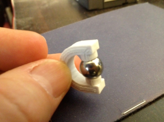
Noodle’s Gripping Toes

noodleTOES

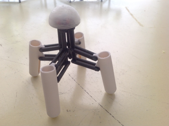
For the past year, the four tawny stalks that NoodleFeet balances upon have remained common pool floaties, 2.5 inches in diameter, hollow, providing nothing more than the obvious support needed to function as legs… but Noodle longs for something greater.

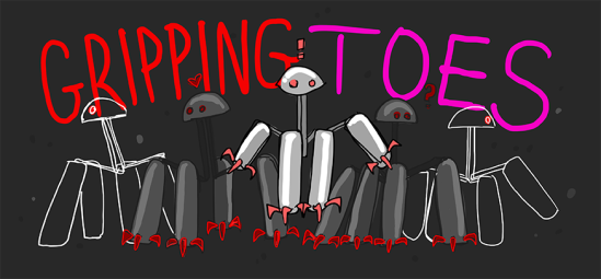
GRIPPING TOES

When Noodle feels threatened, there is little he can do to defend himself. He can beep and perhaps canter away at a slow speed… but he is passive and therefore vulnerable. He isn’t equipped to handle the harrowing task of world domination::cough:: I mean, daily life. To fix this, I decided to add another layer of complexity to Noodle’s most important characteristic: RETRACTABLE GRIPPING TOES for his feet.

A while back, I came across a video of a rock drilling probe concept by JPL. This neat claw attaches itself to a surface by splaying out a hundred or so mini grappling hooks in all directions, which catch on the rock and help anchor the central cylindrical drill in place. I saw this and thought to myself… Noodle needs four of these, as shoes.

Like a good mother, I started brainstorming how to create said shoes. Originally I designed long claw-like toes that rotated out and back, sort of like switch-blades:

Screen Shot 2015-11-11 at 1.50.32 PM

IMG_6632

They fit into Noodle’s original 2.5″ diameter noodle material, and even added stability… but there wasn’t enough area to actually install any motors to actuate things.

With a little bit of trial and error I rethought the whole design and came up with a solution that made use of 3D printed plastic’s flexibility. This new concept worked more like a cat’s retractable claw, and was similar to the drill from the video that had inspired me.

toe1

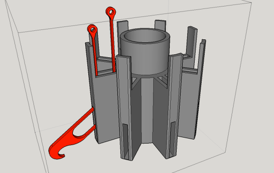
Each individual toe (in red) would be forced through a curved internal channel and out the side via two thin bendable “tendons”:
Screen Shot 2015-11-12 at 2.23.46 PM

How The “Tendons” Work

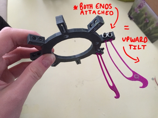
An individual toe has two strands of tendon attached to the back. When the tendons are pulled in opposite directions, it causes the toe to torque upwards or downwards.

Why Do the Toes Need to Tilt Back and Forth?

If the toe goes straight back into the sheath the way it came out, it won’t unhook from whatever its currently gripping. Also, the tip of the toe will likely snag on the edge of the sheath on its way back in. To properly “detach”, the toe should arc upwards slightly as it retracts.

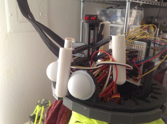
My first prototypes were designed to fit inside the 2.5” diameter noodle material. I was able to make it work, but it didn’t leave much room for the other future functions of his feet (his tongue):

IMG_6656

IMG_6831

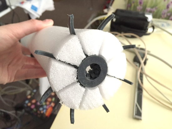
In the end I really needed more space to fit moving parts and hardware. Luckily I have a noodle fairy living with me (Mark) who harvested a larger piece of noodle stock from a pile in his garage. It is 4” in diameter and offers me much more room to play around with! Plus, fatter feet will give Noodle more stability!

IMG_6803

4″ PRO-TOE-TYPE 1.0

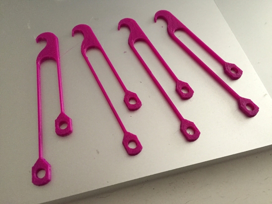
I tweaked my design for the new 4” material and printed my first prototype with a set of eight twinkling magenta toes (I haven’t ordered red filament yet).

IMG_6812

The reason for the tendons being slightly different in length is so that when they are fixed next to one another, it creates the needed outward/upward tilt:

IMG_6840

(so, this is what a toe flower looks like):

IMG_6805

I originally planned to connect both tendons of each toe to a common ring piece (above). When the ring is pushed downward towards the sheath, it would force all of the toes through their channels and outward at the same time. I also added a spring and guide rod (a long screw) below the ring to push it up again once downward force is removed:

The first complete 4″ prototype worked more or less… It certainly passed the “carpet snagging” test:

I learned right away that I couldn’t actually connect both tendons to the same ring and run it through the inside of the sheath without it binding (which now seems pretty obvious). The only way I could get the above demonstration to work was if I left the longer set of tendons sticking out freely, attached to nothing… so that the toe has no preset angle bias as it attempts to travel through the channel:

IMG_6837

However, in order to make it work at this point, all the little purple pieces sticking out had to be pressed down together at the same time first, or else everything would bind up and destroy itself.

4″ PRO-TOE-TYPE 2.0

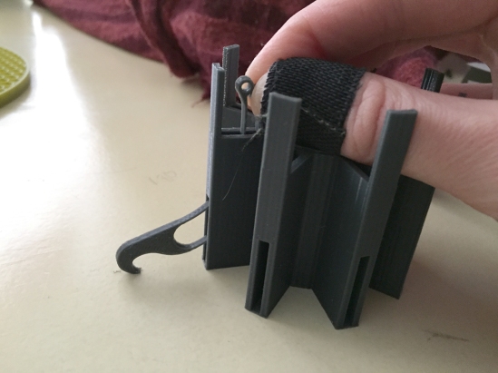
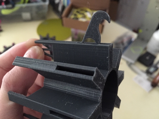
Each tendon should be attached to its own independent ring…

…so that when the ring attached to the inner set of tendons is pressed downward, it causes the toes to tilt upward first as they begin to move down through the channels. Then the top ring hits the second ring below it which the outer tendons are attached to, and then the two travel together pushing the toes outward the rest of the way while maintaining the slight upward torque. This allows the toes to torque gradually as they travel through the channels, without binding up:

IMG_6818

This second prototype (above) is more or less final. I’m going to fine tune it from here, but something very much like this will end up as Noodle’s toe-feet.

The greatest part about this design is that I have nearly 36mm wide of space in the middle to fit his secondary foot function! … ( ? ) … Which is tasting if you didn’t know!

Stay tuned for my next post on the development of Noodle’s TASTING FEET; small silicon wedges that will salivate and lick:

Screen Shot 2015-12-06 at 12.19.14 PM

As I typed that it just occurred to me that I’m pretty much making a tube that can grip onto something while licking and drooling on it. -heh- He’ll have four of these devices. Noodle will be feared by other robots his age.

The only downside to these new complex feet is that I’ll likely have to learn to knit him a pair of custom socks for Christmas. (and I think I actually will) ❤

Read about my past progress on NoodleFeet on my website!

More to come soon!

noodleFeet : Animating the Noodle

I’ve spent the last week learning After Effects. For someone who uses Illustrator on a daily basis, this feels a lot like discovering the magic hat from Fantasia. Among other things, AE allows you to turn a vector based 2D image into a fully rigged character for animation… and it’s even easier to do than you’d think.

I had the idea a while ago to make a series of videos about Noodle and his adventures to Mars… The original plan was that they would be stop-motion shorts, made with a tiny 3D printed version of noodle as the puppet. There is no better terrain to fake as the surface of Mars than our very own desert outskirts… but alas, it is HOT out these days. Even if I could handle the relentless sun (which I can’t because I am WHITE), the PLA that the tiny noodle is made out of cannot. So much for the stop-motion thing.

IMG_2094

For scale (his eyes light up and his feet can hold AAA batteries to power the LEDs):

IMG_2088

I still wanted to make the short videos, so I started thinking back to all the annoyingly complex animation software (like Flash) I’ve used in the past and decided to give AE another go. Since the last time I made an animation using After Effects, they added the puppet pinning feature. It allows you to animate a single layer image by creating a fancy deformation map inside of it that can bend and warp. This means, instead of needing to connect pieces on separate layers together through a process of parenting and careful organization of anchor points… you can just rig one happy image with some bones, and you’re ready to pose your character with cool jello-like properties.

This happened to work SWELL with noodleFeet, as he is essentially a creature of wobble wiggle nature himself. After a long day spent watching tutorials, I got off and running and managed to make my first animation last week.

I still intend to produce a few more of these, but we’ll see how far my patience goes. Though it’s easy to animate, it’s still time-consuming to do it right. Once I attempt to introduce physics into the mix, I may hit a wall… because I’m too cheap to buy one of the fancy addons you need in order to generate the effects of gravity. Bastards.

The best part about having animated noodle walking is that it actually may have helped me understand how to program real-life noodle to walk better. So really, this turned into practical R & D. Ha!

Enjoy getting to know my baby a little better. He is the feet.

noodleFeet : Proof of Concept

Last week I started building a new robot who I’m calling noodleFeet! He is essentially a spider-type walker who will locate nearby legs, approach and then lean on them. In addition to having that specific purpose, he needs to look a particular way. I’ve been drawing him in the margin of my notes for weeks now, so he’s become something of a character to me:

noodle2

In order to make a robot that does these things, I need to design the mechanism itself and how it will be attached to the motors driving the motion (challenging and fun). At the same time I need to learn about Open CV and figure out how to make a computer recognize all the different shapes that legs come in. This will involve a camera and some coding (hard and not fun). With these two elements combined, I’ll eventually end up with a leg hugger…… or leaner. I’ll talk about the details of those steps when I get to them.

To get started, my challenge for the weekend was to solve how to make the legs of the robot itself. I wanted to come up with a reverse knee-joint capable of folding into a single-stick. This took about three of four revisions to get right, at which point I went on to 3D print four copies for the proof of concept.

IMG_1420

The proof of concept is nothing more than a rough servo bracket that holds all of the motors in place at the point where the four legs attach to them. With these parts alone I was able to construct something that looks surprisingly already very much like the end product I’m aiming to create. It still isn’t a working prototype however. For this, my concerns were mainly measurement and proportion:

noodle

I’ve gotten away with using 3D printed parts on many of my projects, but for this one plastic isn’t going to cut it. Even though the design is mechanically sound (I believe) and I could have wired some servo motors up to see some motion, the flimsy plastic legs don’t seem like they’d be able to support the combined weight of the motors… so I didn’t. Because of that, the next step is to replace the crucial parts that support the most weight with aluminum pieces. So I’ve gone ahead and ordered some hollow pipe and bearings for a more sturdy, motion-ready second prototype. In fact… the materials arrived today, so it’s a good thing I got documenting this out of the way!

Hopefully with my next post I’ll have video of noodleFeet making his first steps… or wiggles. You can see him in this illustration I recently drew to the right of our car:

wtfWestCoastSmall

jellyBot : Rolley (the second prototype)

Ok, so the proof of concept I worked on back in October looked awesome, but it couldn’t really move on its own… and there were a couple of reasons why:

  • I had mounted standard servos on the drive shaft instead of the continuous rotation type. I found out you need more than a breadth of 180 degrees to make a rack and pinion move far enough to do anything useful!
  • Also, my drive shaft needed some roller bearings to tension the rack down onto the pinion in order to stop all the slippage.

Since both of these things involve the mount of the motors specifically, I took the time to completely redesign that whole part to be more solid in general… after all, it is the very core of the robot- therefore the most important part! Tighter tolerances = happy jelly.

So what I ended up making was a set of brackets that both servo motors mount to… the roller bearing tensioner is a separate piece that screws into both, bridging the two and making it one solid piece:

IMG_1316

The extra gear bit (that kinda looks like a spur in the picture above) was added to help keep the rack in alignment, but it ended up causing more problems than solving them… so I removed it. The final working rendition had a roller bearing slightly above and below the pinion itself… instead of one directly on top of it:

IMG_1328

After these changes were made I hooked one of the new motors up to an arduino to test whether or not the thing moved… which it didn’t. =[ BUT- it wasn’t because of the improvements I had just made. I now had a new problem to solve.

SO- the bit that is actually supposed to be moving is a sort of vertebrae or disk that slides up and down on the metal rails which the stationary servos are mounted to. One of these disks is attached to the end of each rack, but only on one side. As this goes…. when the rack moves, it tips the disk slightly at an angle… which causes it to bind on the rail rather than slide up and down it at an ideal 90 degree angle. Eh.

The solution apparently was to add some linear bearings… which I didn’t have on hand- so I faked it and just added some cylindrical tubes to the part in CAD and reprinted them. This actually worked extremely well. Not as well as linear bearings, but it did get the thing working at last:

IMG_1324

Accept… a third problem appeared at this point. Now that the properly tensioned rack and pinion was actuating the properly guided disks up and down the rails… there was really no quick way to calibrate the motors back to center every time I unplugged the power. Eh. Since these are continuous rotation motors, there is no center… so I had to manually pluck the pinion off and guide the rack back down by hand…

Which sucked. So… it was time to graduate from my uber basic sweep code to something with feedback. I wired up four buttons on my breadboard and Mark helped me write some code in Arduino so that each of the two servos had a switch for up and down. Now I have absolute control over the range of the motors!

So, the new drive shaft more or less works mechanically, which is swell. The next phase of development will include adding limit switches and a way for the jelly to zero itself out when it needs to… as well as some motor choreography so it actually jellies like a jelly is supposed to.

Robot Army : From Tupperware to 3D Printing

progression-01

When I moved back home from art school in Chicago, one of the biggest drags was no longer having access to the beefy machine shop that was down the street from my apartment. I went from playing with a room-sized lathe and mill to having little more than a $20 soldering iron and dremel at my disposal. It seemed my metal-cutting days were going to end as soon as they started… well enough, this didn’t stop me from making the things I wanted to. I just had to use plastic now instead. Luckily for me, plastic was in abundance at my parent’s house. My mom hordes take-out containers and tupperware, so I had a bottomless stash to carve up.

Still pursuing my vision of creating the field of robotic flowers, I was trying to refine the design of my ‘steam’ into something a bit more controllable. At some point I ran across a video of a small delta robot someone had made on the internet. As I watched it bob up and down in that special twitchy, impatient way… I fell in love. From that moment on I became obsessed with building my own!

Long story short… Everything became a potential shape. I-beams. They’re everywhere :

hangerArms1

I used a lot of crappy plastic hangers. They made great paddles to connect onto the servo horn like you see below :

hangerArms2

In the beginning, mechanical joints mystified me. I didn’t quite understand what was going on with how a delta robot moved, so this prevented me from being particularly inventive with what I used to connect all the piece together. I read on a forum someplace that you could use 4-40 swivel ball links, which you can get from a hobby store… so I bought myself a set to try out. The thing is, they work great but they cost way more than any piece of plastic should (like… $18.00 for 12 of them. Just enough for one robot). ALSO, they require tiny spacers on either side of the ball. This helps give the rod a breadth of motion without smacking into the plastic piece its rotating in. The sucky part is that the pack of 12 joints form the hobby store only comes with half the number you’ll need (for a delta you need one on each side). The links are the pieces at the end of these 4-40 rods :

miniProgress6

In order to make a whole field worth like I was planning, I’d need to find a cheaper alternative that was less hardware dependent. For now though, these worked. I attached my paddles made of hanger bits to these arms :

progress2

The next step was figuring out how to mount the delta robot. I realized that the servo motors would have to be elevated so that the paddles could swing below the angle of the table top. I didn’t have anything fancy to use at the time, so I took a pasta togo box from the cupboard and cut into it with my dremel to get some nice clearance slots :

baseMod1

The next thing to figure out was how on earth I was going to mount the actual motors onto my base. A normal person would have used L-brackets of some sort, so I did precisely that… except again, mine were made from strips of plastic cut from togo boxes. >.<

baseMod3

As you’ve guessed… the end effector was also eventually made from cut pieces of plastic. My first working prototype was practically a togo box with motors :

This was a great feat making my first functioning delta robot. I was proud of its frumpiness because though it wasn’t mechanically solid like a robot made of metal, it still worked. Of course, I wasn’t going to make a whole field of delta robots out of togo containers (although I probably could have because my mom surely had enough to do so). The next step was to shrink the design and refine the method so it could be repeated with ease.

My next prototype was still made of plastic, but I got classy and went to the Container Store and invested in some nice cylindrical boxes. These would become the new bases for my robots :

miniProgress3

I repeated the same steps, cutting the clearance slots for the paddles and making small L-brackets to mount the motors to the base. The base the motors were connects to was actually the lid of the container so you could remove it and use the bottom part as an enclosure for the board running it (clever!) :

origin5

I had aspirations of building three of this particular prototype… to see if they could all be networked together and potentially all run at once :

progress7

The two-dollar micro servos I bought from some nondescript hobby store (imported from China) were terrible quality. Though my second prototype worked, it moved like it had Parkinson’s disease. =/

I wasn’t really happy with this… but two dollars a motor was all I could afford at the time (I was still living at home with the folks). Eager to try again when I could invest in some more quality materials… I started rethinking the entire design.

origin3

For the rest of the summer I meditated on what I had learned. The little blue servos from China stripped in a matter of days while I was testing out code… So I was left with nothing more than a delta shell.

One extremely fateful day I met the people of SYN Shop at an art faire downtown. The hackerspace was just a glimmer in someone’s eye at the time and was run out of the garage of the man who is now my collaborator (Mark Koch). They invited me to stop by some time and show off whatever I was working on. Eesh. Even though I was embarrassed and apprehensive, I brought the mangled corpse of my second delta prototype to show to people. In spite of its appearance, my gimpy child got a lot of attention for the mere fact that I managed to pull off making a delta robot from garbage. Mark had always wanted to build his own pick and place machine, so seeing my creation urged him to get off his butt and make one of his own.

This is when the discovery of 3D printing changed my life. Mark suggested that I design my delta’s parts in CAD and of all things…print them. I was familiar with 3D printers, however the one my art school had was huge and they charged an insulting amount just to produce tiny things with it. Up until then, I had no clue that desktop 3D printers even existed, so my mind was blown when I saw his Replicator for the first time. The usefulness of this tool was revolutionary. I could continue building my robots in plastic like I had been, but I wouldn’t have to machine my parts as if they were metal. How easy!

I spent the rest of the year learning Sketchup. This is a free piece of software that I highly recommend to beginners. It isn’t as powerful as Maya or Solidworks, but its intuitive so you can start making things with it immediately. You basically draw 2D shapes like you would in Illustrator and then extrude them upward to make basic geometrical objects. You can edit things from there of course. If you’re looking to design mechanical parts, this tool is a wet dream, but be patient because it has it’s irritating quirks and limitations.

origin1

One day during CES in 2013, Mark came onto something rather brilliant while we were discussing our designs over margaritas. The solution for those expensive and convoluted swivel ball links (that I had been stuck using) was to use some sort of U-joint that could compress onto ball bearings and twist freely in all directions. The idea was simple and genius :

origin14

This was an important quality because now we could completely divorced ourselves from having to source out any hobby parts. This means aside from some hardware, we no longer had to buy link joints, or cut rod in order to make the robot work. Everything was designed in CAD. Everything was 3D printed. My cost went down significantly, and at last I had the perfect model which I could realistically expect to afford building in mass… and all I had to do was hit ‘print’.

Once we mastered this technicality, it was a matter of implementing it throughout our designs. My personal delta robot went through many…….. many revisions before it became the thing it is now :

origin12

It was at some point last spring that our robots reached their pinnacle. My first complete and polished delta made from 3D printed parts was named Jeden (after the Polish word for one), and Mark’s hanging delta robot was named Amber (after an inside joke Mark and I had at the time). This was the revision of Jeden right before I got my neon yellow filament in the mail :

origin13

We had been working so hard that our collaboration was getting noticed by the others in our community and our friends from SYN Shop decided to interview us about our ‘rivalry’ for their first podcast :

We hadn’t really thought of one another as collaborators (or rivals for that matter) until that point in time. Once it was brought to our attention however we took off like rockets loaded with beer and nitrous. We’ve been working together ever since and within a year brought a delta robot kit to market… which is the thing I’m promoting so heavily right now on Kickstarter.

deltaDiagram2

This campaign is not only getting us our funding to build that elusive art installation I’ve been wanting to create, it’s also the introduction of our new company to the maker community. Mark and I don’t expect this will be our last kit. We’re sort of hooked on this process now and already have plans for what’s next. We are Robot Army LLC and it looks like we’re here to stay =]

It’s been a fantastic journey. I’m getting to strike a couple of goals off my bucket list. I started this blog two years ago to prove to the world (and myself) that anyone with a little bit of drive and passion can bring something from their dreams into reality… even coming from a position where you lack experience or expertise. There is a wealth of open knowledge and support out there to be drawn upon. If you choose to use it, anything is possible.