jellyBot : Rolley (the second prototype)

Ok, so the proof of concept I worked on back in October looked awesome, but it couldn’t really move on its own… and there were a couple of reasons why:

  • I had mounted standard servos on the drive shaft instead of the continuous rotation type. I found out you need more than a breadth of 180 degrees to make a rack and pinion move far enough to do anything useful!
  • Also, my drive shaft needed some roller bearings to tension the rack down onto the pinion in order to stop all the slippage.

Since both of these things involve the mount of the motors specifically, I took the time to completely redesign that whole part to be more solid in general… after all, it is the very core of the robot- therefore the most important part! Tighter tolerances = happy jelly.

So what I ended up making was a set of brackets that both servo motors mount to… the roller bearing tensioner is a separate piece that screws into both, bridging the two and making it one solid piece:

IMG_1316

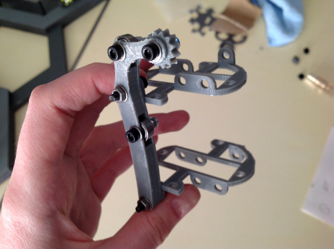
The extra gear bit (that kinda looks like a spur in the picture above) was added to help keep the rack in alignment, but it ended up causing more problems than solving them… so I removed it. The final working rendition had a roller bearing slightly above and below the pinion itself… instead of one directly on top of it:

IMG_1328

After these changes were made I hooked one of the new motors up to an arduino to test whether or not the thing moved… which it didn’t. =[ BUT- it wasn’t because of the improvements I had just made. I now had a new problem to solve.

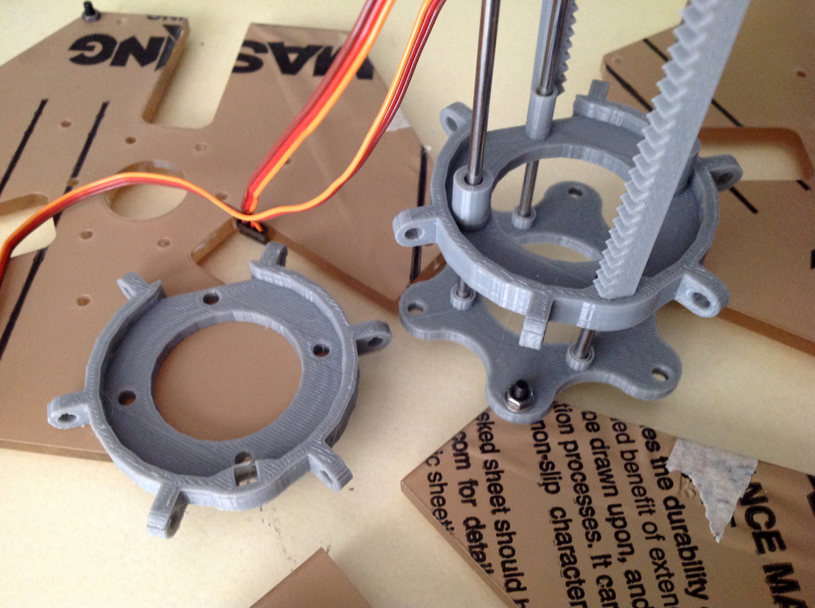
SO- the bit that is actually supposed to be moving is a sort of vertebrae or disk that slides up and down on the metal rails which the stationary servos are mounted to. One of these disks is attached to the end of each rack, but only on one side. As this goes…. when the rack moves, it tips the disk slightly at an angle… which causes it to bind on the rail rather than slide up and down it at an ideal 90 degree angle. Eh.

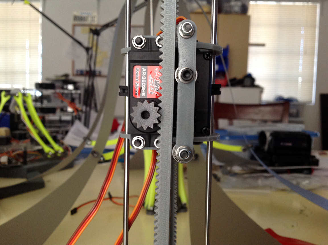
The solution apparently was to add some linear bearings… which I didn’t have on hand- so I faked it and just added some cylindrical tubes to the part in CAD and reprinted them. This actually worked extremely well. Not as well as linear bearings, but it did get the thing working at last:

IMG_1324

Accept… a third problem appeared at this point. Now that the properly tensioned rack and pinion was actuating the properly guided disks up and down the rails… there was really no quick way to calibrate the motors back to center every time I unplugged the power. Eh. Since these are continuous rotation motors, there is no center… so I had to manually pluck the pinion off and guide the rack back down by hand…

Which sucked. So… it was time to graduate from my uber basic sweep code to something with feedback. I wired up four buttons on my breadboard and Mark helped me write some code in Arduino so that each of the two servos had a switch for up and down. Now I have absolute control over the range of the motors!

So, the new drive shaft more or less works mechanically, which is swell. The next phase of development will include adding limit switches and a way for the jelly to zero itself out when it needs to… as well as some motor choreography so it actually jellies like a jelly is supposed to.

jellyBot : Racky All in one Piece

IMG_1152

This weekend I started printing the newly redesigned pieces for my jellyfish robot. I got about 90% finished by Sunday, but not enough was intact to start testing out whether or not the design will move like it should.

Yesterday, I scraped together the short end pieces leftover from old roles of filament to finish printing the rest of the tiny arms for Racky. Now that I’ve added a slight curve to the length in addition to the U joint at one end, it was a pain deciding how to print the piece without ended up with a pile of pelvic fur. I had to position it rocketing off the build plate with some support material, which had a 50% success rate, (which sucked as I was nearly out of yellow). In spite of the failed attempts, I got them all done… just in the knick of filament :

IMG_1138

Once these small arms were added to the body, I needed to come up with a better way to attach the tendrils than with twist ties (like in my old prototype). So, I made a little U joint piece that could screw onto the under side of each arm :

IMG_1145

At this point I realized that the jelly as a whole needed to be disassembled so that I could secure the motors onto the steel rods somehow. I had the idea to use some of the square rubber grommets that came with the servo motors to slide onto the rod, filling the small gap between the two and wedging them in place :

IMG_1143

Once done, I was able to put the rest of the jellyfish back together around this piece. The last bits to screw together where the tendrils to the short curvy arms I had just attached to the body :

IMG_1150

Everything looks nice and I’m sorta confident it will work to some degree… but before I can hook the motors up and do any sort of testing, I need to design that tensioner for the rack and pinion. Otherwise nothing is going anywhere. Alas, I’ll get to it!


My New jellyBot Prototype, Racky


IMG_1097

About a year ago I started building a robotic jellyfish inspired by Festo’s submergible AquaJelly. I was just beginning to figure out how to get the thing moving when I got sidetracked with the prospect of launching a Kickstarter campaign and dropped the project cold. During this whole long year while I’ve been fulfilling the said Kickstarter, this poor jelly prototype (“Boney”) has watched silently from a distant shelf in the workroom, begging me to pick it up again. Finally this weekend I was able to spend some time giving the old parts a makeover… in yellow.

I added a nice gentle curve to the moving pieces, taking after the design of its cousins, the delta robots :

IMG_1040

IMG_1042

Last year I decided to use a rack and pinion to get the parts to move in leu of Festo’s fancy linear actuator that they showcase in their model. Never having used, let alone designed a working rack and pinion before, this took some fussing about to get just right. The two servo motors I chose to drive the jelly’s motion are attached to a fixed central core of steel rods which two separate radial disks glide up down upon. All of the jelly’s flowing arms will be attached to the elbow of the mechanical arms, and as the disks these arms are attached to move back and forth, towards and away from each other, a sort of circular pumping motion is made.

IMG_1079

The two rack and pinion sets are in place now, each on opposite sides from one another moving different pieces in opposite directions. The rack passes through a slot in the opposing central disk, allowing it a deeper breadth of motion as well as keeping it in place. The only thing I seem to be missing at this point is a tensioner to press the rack against the gear on the driveshaft of the motor, so I have plans to whip one up later tonight.

On my old prototype, I used plain long strips of sheet ABS as stand ins for the jelly’s long flowing arms. They worked more or less, but weren’t very nice to look at :

IMG_4097

For this rendition of the bot, Mark offered me some of his old shelf liners from the garage to use. These happened to be an awesome semitransparent gray that matches the printed parts of the jelly perfectly! I decided on an elongated spade shape for the tendrils this time :

IMG_1046

These pieces connect at one end to a small ring, creating the umbrella of the jelly (the delta robots watch from the side in aw…) :

IMG_1056

The center of the umbrella mounts to the top portion of the drive shaft with a fancy pants shape sandwiching it in place like so :

IMG_1058

Once I design my tensioner for the rack and pinion and finish printing and attaching the rest of the jelly’s small arms (all of this depending on whether or not my printer stops being a butt) I can then start working on some test code to get the thing moving! I have no idea really if my design will work at all… I’ll just have to wait and see. For now though, it’s getting acquainted with all of its brothers and sisters in the war room. =]

IMG_1078

My next post will likely be about whether or not I succeeded mechanically in getting the jelly to do what its supposed to. Cheers!

IMG_1116


Robo Jelly : Progress

IMG_4097

Even since I first saw the Festo Aquajelly I’ve wanted to make one of my own. With the arrival of our brand new Flash Forge 3D printer…. this week seemed like the right time to start prototyping.

If you haven’t ever seen the Festo Jelly, I advise you to check out the video below. This company inspires me. They sell fancy pneumatic parts and actuators but for shits and grins they make amazing robots that mimic the organic movement of animals. I mean, in a fantasy I’d come stay at their headquarters and make things with their parts for days on end…but who that I know of wouldn’t?

festos

I sat down earlier this week and drew up some parts in Sketchup. With a couple of revisions I made this jelly skeleton. It took about an hour to print one set of arms (I needed six total). So at around midnight last night I was able to assemble the whole thing. Below is one set of arms :

IMG_4089

Three sets of arms :

IMG_4091

Before heading to SYN Shop for robot night tonight I added some thin strips of white ABS to the exterior to simulate the skin…. just to get an idea of how the things works mechanically once all the parts were attached to each other….

IMG_4103

I have no idea how I’m going to actuate this thing yet… but we’ll figure it out in the next week. Wish me luck!

IMG_4105